ZX-ATKEY - V.2 (c) 2005 wilf rigter
A ZX81 interface for the AT keyboard
After an 8 year hiatus, I can finally finish the AT keyboard to ZX81 interface.
The PC printer port of the original ROMKEY article has now been replaced
with a PICAXE 18X chip that is programmable in BASIC and has build in
support for the AT keyboard. This is also my first PICAXE project and I am
happy to report that the PICAXE hardware and documentation is easy to use
and the software is easy to program. The BASIC KEYIN and KEYLED functions
make interfacing the keyboard and decoding the messy protocol reasonably
straight forward.
The 18X ZX-ATKEY design allows use of an AT keyboard as a transparent
substitute for the old ZX81 membrane keyboard. In addition, the PICAXE
has a true asynchronous port that allows the ZX81 to communicate with
a PC at up to 4800 baud. The hardware for this project is amazingly simple
consisting of a PICAXE 18X and a 27C256 EPROM and some passive components.
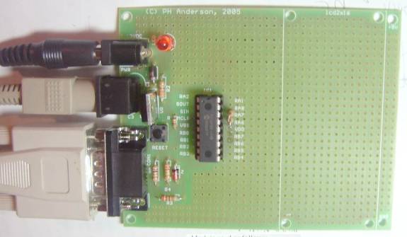
I build the ZX-ATKEY circuit on a prototype board available from Peter Anderson,
which I modified slightly to mount the PS2 connector next to the DB9 and DC
power supply connectors.
THE ZX-ATKEY CIRCUIT
5V 5V 5V
ZX81 PCB REAR ZX/ASCII ROM |
| | AT KBD
EDGE CONNECTOR 27C256 1M
PICAXE18X 4.7K 4.7K PLUG
______________ |
0.1 _________ |
|
+5V ---> 5V | CE
|20-+-||--13|OUT7 | |
| DATA
D0 -----------11| D0 A8 |25--------6|OUT0
IN7|16-+---|--------o
D1 -----------12| D1 A9 |24--------7|OUT1
IN6|15_ | 0V-o
o-5V
D2 -----------13| D2 A10 |21--------8|OUT2
| `---+------o o
D3 -----------15| D3 A11 |23--------9|OUT3
| CLOCK
D4 -----------16| D4 A12 |2--------10|OUT4
|
A8 -----------10| A0 A13 |26-------11|OUT5
|
A9 ------------9| A1 A14 |27-------12|OUT6
|
A10 ------------8| A2 |
| |
A11 ------------7| A3 D5 |17-------17|IN0
|
A12 ------------6| A4 D6 |18-------18|IN1
|
A13 ------------5| A5 D7 |19--------3|IN2
|
A14 ------------4| A6 |
| SOUT|2--180---- SERIAL OUT
A15 ------------3| A7 | 5V |
SIN|3--22K--+- SERIAL IN
A0 -->|--+----22|OE Vdd|28---|---14|Vdd |
|
1N4448 | | Vpp|1____| |
RESET|4 __ 10K
RD -->|--+ |_____Vss______|
| |___Vss___| |
|
|
|14 | |5 | 0V
IORQ -->|--+---[4.7K]----| === 0.1 | |
0V
____________________|_____________|__________| |
RST
_______________________________________________________|
HOW ZX-ATKEY WORKS
The ZX81 uses the Z80 address lines A8-A15 to scan the membrane
keyboard matrix by pulling each keyboard row low with an address line
and reading the column data through the ULA keyboard port on D0-D4.
The I/O address for the keyboard port is FEh.
The AT keyboard transmits serial data together with a clock signal to
the PICAXE IN6 and IN7 lines. This data is sent in the form of a unique
8 bit SCANCODE value together with START, STOP and PARITY bits. The
PICAXE receives the serial data, checks for transmission errors and
translates the AT keyboard SCANCODE into a 7 bit ASCII value which is
output on OUT0-OUT5 together with an active low "keydown" signal on
OUT7.
The ZX/ASCII EPROM converts the ASCII code, which is connected to
EPROM address lines A9-A12 to address a block of 8 bytes containing
the ZX81 scan code. The OUT7 pin is connected via a R/C network to
pulse CE active low for 100ms when a key is pressed after which CE
returns to inactive High. This R/C conditioned pulse is necessary so that
the PICAXE program can quickly return to the KEYIN routine which waits
for the next key code transmitted by the AT keyboard.
The ZX81 addresses the EPROM when the normal ZX keyboard I/O port
FEh is read with an active low on the EPROM OE line and by scanning the
8 EPROM bytes with the A8-A15 lines connected to the EPROM A0-A7 pins.
With CE pin low and OE pin low the EPROM D0-D4 data lines are enabled
and read on the ZX81 data bus in parallel with the ULA keyboard data.
This ZX-ATKEY project is a work in progress and will be completed in
stages. Here are some pictures that show the PICAXE protoboard with
the PS2 connector added.
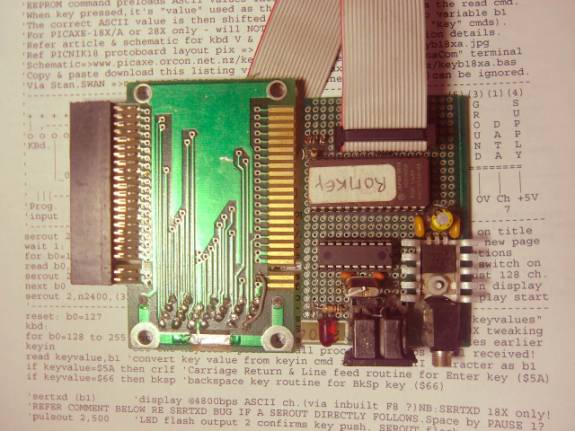
I am currently experimenting with a short program by Stan Swan
called keyb18xa.bas that demonstrates the keyboard function and
ASCII conversion to test the keyboard interface on the protoboard.
Next the EPROM hardware and ZX81 interface which was
previously tested will be added similar to the 16C84 version.
Then I will modify the PICAXE code to access the EPROM instead of
the serial port at which point the interface can be tested with a ZX81.
Then the code for ZX81 control of the PIC serial port and the code for
data communication using the EPROM D5-D7 lines will be added.
I will try using a blog style progress report. But each stage will be
documented posted as a series of updates to this article on the
ZX-ATKEY project.
enjoy
wilf