2K ROMPATCH FOR A
TS1000 WITH 16K-64K RAMPACK
wilf rigter
06/2005
This
is part 1 of two articles inspired by the MemoHRG module.
That
unit uses the following components (thanks to Michael Anton)
PAL16L8-4CJ
PAL14L4-2CH
74LS37
Quad 2 Input NAND Gate
74LS20
Dual 4 Input NAND Gate
74LS74
Dual D Flip-Flop
74LS125
Quad Transceiver
74LS373
Octal Latch
2716
2KB EPROM
7805 Voltage regulator
Conspicuously
absent from the parts list is a STATIC RAM chip, which
made
me curious indeed how it manages to display a 248x192 true hires
screen
using the standard 16K dynamic RAM pack. Moreover, the docs
indicate
that the hires display can be anywhere in memory without regard
to
address boundaries!
I
don’t have this Memotech unit on hand to actually reverse engineer it,
which
is just as well since it allows me design a work-alike circuit based
on
the description of operation and a cursory analysis of the HRG EPROM
disassembly
found here.
While
I work out the final details of the HRG portion to be posted in part 2,
I
would like to share some of the buried treasure I uncovered thus far.
You
may be surprised to find that the MemoHRG unit uses the ZX81 internal
RAM
chip to patch new video routines over the ZX81 ROM code.
The
MemoHRG unit was designed for the ZX81 so it only liberates 1K of RAM.
The
TS1000 comes equipped with a 2K internal static RAM which the
ROMPATCH
circuit can fully utilize. An optional resistor and diode decodes
the
A10 line to make the ROMPATCH circuit compatible with a 1K ZX81.
When
an external 16K RAMPACK is attached the internal RAM is normally
disabled
by connecting the RAMCS line to Vcc.
The
MemoHRG goes between the ZX81 and the RAMPACK and decodes the
0000
–0400h for the RAMCS line, probably using one of the two PALs.
The
ROMPATCH circuit shows a simpler method, which is functionally similar.
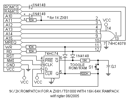
An
8 input OR gate (74HC4078) decodes a low on A11-A15, MREQ,
and
RD or WR low. The OR gate has two complementary outputs, of
which
one is connected to RAMCS and the other is used to disable the
ROMCS
line.
On
power up the ROM is accessible for reading with /RD and /RFSH
while
the RAM is accessible for writing with /WR. This condition
allows
the bottom 1K of the ROM to be copied to RAM with:
LD
HL, #0000
LD
DE, #0000
LD
BC, #0400
LDIR
This
is the snippet of code of the initialization subroutine at 2442-2474h
in
the MemoHRG EPROM disassembly that made me realize what the
clever
folks at Memotech were up to.
The
remainder of that code segment is used to format a HRG display file
and
change 4 bytes (only!) of the Sinclair video Routines to make them
compatible
with the HRG format.
The
MemoHRG hardware is designed for SLOW mode HRG display and
this
article assumes that the ZX81 is in the SLOW mode. It is essential that
the
RAM is prepared with ROM contents and video patches before the
RAM
is switched in place of the ROM.
Half
of a 74HC74 is used as a pushbutton (S1) conditioner that toggles
between
RAM and ROM occupying the 0000-0800h address space.
The
0.1 cap charges up through the 1M resistor to a state opposite the
current
state of the flip-flop. When this cap is connected to the D input,
the
next NMI pulse will change the state of the flip-flop and enable the
RAM
to be read in of the lower address space of the ROM. Each push
of
the switch will toggle between RAM and ROM mode and displays the
corresponding
different video screen. A LED and resistor can be added
to
indicate which mode is active.
The
NMI pulse is used to synchronize switching of video mode during
program
execution time to avoid conflict that would result if switching
occurred
during live video display.
The
final detail to observe is the way that the /RD and /WR lines are
controlled
with the series diodes and resistors connected to the flip-flop
outputs.
The
OR gate true output controls the RAM CS line when low, which
happens
when all OR gate inputs are low. When the RAMCS line is active
low
the ROMCS line is disabled with the OR gate inverted output.
When
the flip-flop Q output is high, as would be the case after reset or
power-up,
the /WR line selects the RAM when /WR is low. When the
/Q
output is high, /RD selects the RAM
when /RD is low.
The
ROMPATCH design applies equally well to other applications that
can
benefit from making changes to the first 2K of ROM code.
ROMPATCH
is a small part of the MemoHRG design and the video part is
very
interesting indeed. However the strange 248x192 format, with two
additional
bytes of “control code” required at the beginning of each
horizontal
line of the display file is awkward design and can be an obstacle
to
smooth manipulation of the video display.
Turns
out this screen format is not necessary at all and next we will take a
Somewhat
speculative look at the HRG hardware and present an alternative
256x192
screen display version that requires no control codes in part 2.
enjoy,
wilf